
Pin Diagram
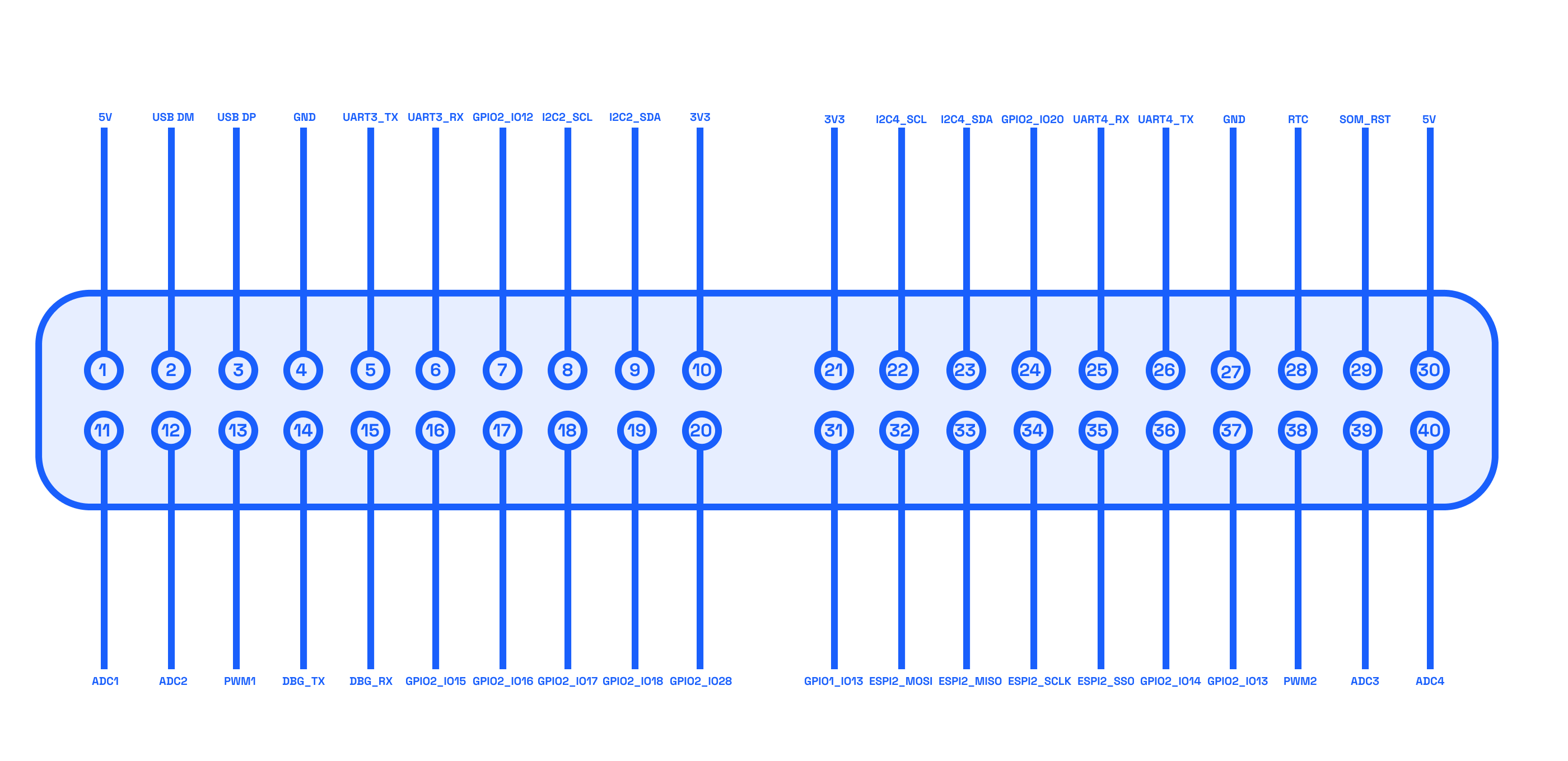
The Mecha Comet device features a versatile General-Purpose Input/Output (GPIO) interface, allowing users to connect and control a wide range of peripherals, sensors, and communication modules. The GPIO pins support multiple protocols, including UART, I2C, SPI, ADC, USB and PWM, making it a flexible solution for embedded applications.
Below is the pin diagram illustrating the available connections on the Mecha Comet device:
Pin Table
The following table provides a detailed breakdown of each pin's function and possible usage:
| Pin Number | IO | Description |
|---|---|---|
| 1 | 5V | Power supply (5V output). |
| 2 | USB DM | USB Data Minus (D-) for USB communication. |
| 3 | USB DP | USB Data Plus (D+) for USB communication. |
| 4 | GND | Ground connection. |
| 5 | UART3_TX | Transmit (TX) pin for UART3, used for serial communication. |
| 6 | UART3_RX | Receive (RX) pin for UART3, used for serial communication. |
| 7 | GPIO2_IO12 | gpio (active low). |
| 8 | I2C2_SCL | Clock (SCL) line for I2C2 communication bus. |
| 9 | I2C2_SDA | Data (SDA) line for I2C2 communication bus. |
| 10 | 3V3 | Power supply (3.3V output/input depending on the design). |
| 11 | ADC1 | Analog-to-Digital Converter input channel 1. |
| 12 | ADC2 | Analog-to-Digital Converter input channel 2. |
| 13 | PWM1 | Pulse Width Modulation (PWM) output channel 1. |
| 14 | DBG_TX | Debug UART transmit pin, typically used for logging/debugging. |
| 15 | DBG_RX | Debug UART receive pin, typically used for logging/debugging. |
| 16 | GPIO2_IO15 | gpio (active low). |
| 17 | GPIO2_IO16 | gpio (active low). |
| 18 | GPIO2_IO17 | gpio (active low). |
| 19 | GPIO2_IO18 | gpio (active low). |
| 20 | GPIO4_IO28 | gpio (active low). |
| 21 | 3V3 | Power supply (3.3V output/input depending on the design). |
| 22 | I2C4_SCL | Clock (SCL) line for I2C4 communication bus. |
| 23 | I2C4_SDA | Data (SDA) line for I2C4 communication bus. |
| 24 | GPIO2_IO20 | gpio (active low). |
| 25 | UART4_RX | Receive (RX) pin for UART4, used for serial communication. |
| 26 | UART4_TX | Transmit (TX) pin for UART4, used for serial communication. |
| 27 | GND | Ground connection. |
| 28 | RTC | Real-Time Clock input, typically used for battery backup or external clock signals. |
| 29 | SOM_RST | System-on-Module reset signal (active low). |
| 30 | 5V | Power supply (5V output/input depending on the design). |
| 31 | GPIO1_IO13 | gpio (active low). |
| 32 | ESPI2_MOSI | SPI2 Master Out Slave In signal for SPI communication. |
| 33 | ESPI2_MISO | SPI2 Master In Slave Out signal for SPI communication. |
| 34 | ESPI2_SCLK | SPI2 clock signal for SPI communication. |
| 35 | ESPI2_SS0 | SPI2 chip select signal (Slave Select 0). |
| 36 | GPIO2_IO14 | gpio (active low). |
| 37 | GPIO2_IO13 | gpio (active low). |
| 38 | PWM2 | Pulse Width Modulation (PWM) output channel 2 (alternative pin). |
| 39 | ADC3 | Analog-to-Digital Converter input channel 3. |
| 40 | ADC4 | Analog-to-Digital Converter input channel 4. |
Notes
- Power Pins (5V & 3.3V): These provide power to external peripherals.
- GND (Ground Pins): Must be used as a common reference point for electrical circuits.
- UART (Universal Asynchronous Receiver-Transmitter): Used for serial communication.
- I2C (Inter-Integrated Circuit): A common communication protocol for sensors and peripherals.
- SPI (Serial Peripheral Interface): A high-speed serial communication protocol used for displays and storage devices.
- GPIO (General Purpose Input/Output): Configurable digital input/output pins.
- PWM (Pulse Width Modulation): Used to control brightness, motors, and servos.
- ADC (Analog-to-Digital Converter): Converts analog signals (e.g., from sensors) into digital values.